
The first telescopic mirror mount I ever saw was part of my 1964 Edmund “Sky Conqueror” 4” F/10 reflector. I remember nothing about it, other than I could use it to adjust the mirror’s tilt. (I was too busy conquering the sky to notice much else!) The next mirror mount was part of a very much up-market 8” f/4.5 Cave Astrola. It, too, was adjustable with springs and wing nuts. I learned a lot about optical system alignment from that mount and the diagonal mirror’s mount. Mostly, I learned that there were a lot of things that could become misaligned in a Newtonian telescope.
Every time I threw the Cave into the car to take it to some observing site, the optics shifted and needed to be aligned before I used the telescope. At the time, I just figured that that’s the way things were. Reflectors need to be constantly aligned, and Refractors never needed alignment. There were so many big things to learn in Astronomy, I never wondered why this should be the case.
I bought the three volume set of Amateur Telescope Making, and learned that mirror mounts also support the mirror’s weight. Well, OK. Big mirrors seem to have lots of triangular pads, and small mirrors have three. My 8” Cave had three cork pads at the 70% zone. It had three cork-covered retaining clips to keep the mirror from falling out of the cell when the telescope pointed down. I carefully adjusted these so they would not quite touch the mirror’s front surface. This meant the mirror was basically free to slide around, but I thought that was normal, too.
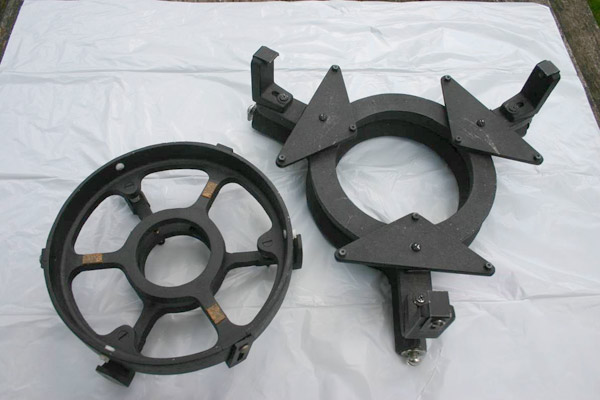
Above is a picture of the mount and the mirror, along with a whiffle-tree mount. Note the three white nylon set screws in the Cave mount, to the left. These were intended to keep the mirror from sliding around, but since the mirror blank had strongly tapered sides, tightening these had the effect of popping the mirror out of the mount. Even as a teenager, I knew this was not good. Nevertheless, this was state-of-the-art for amateur telescopes, and this state of the art didn’t change until the advent of big, thin Dobsonian mirrors. At which point, the art got significantly worse.
Around 1981, Doug Nelle got a gigantic 17.5” mirror made by Coulter Optics, and if I’m not mistaken, it was originally mounted on a disk made of two layers of 3/4” chip-board, and was fastened to it using several wraps of duct tape around its edge. Kinematics tells us that two rigid bodies will contact each other at three points. I’m still wondering where those three points were on the Coulter mirrors. Not where they were supposed to be, I’ll bet.
If you are trying to support a long beam (like a strip of telescope mirror, or a twenty-foot long piece of wall molding) and intend to keep it very straight, you’ll have to support it at enough points to keep the sag that the beam experiences between supports below your bend requirements. It helps if your beam is fairly thick (hence the 6:1 diameter-to thickness ratio recommended by old telescope makers), and it also helps to have lots of supports. Clearly, the beam thickness and number of supports are related.
I was asked to redesign the mount of a telescope mirror which was boosted above the atmosphere. The original designer had wanted to keep the number of supports to a minimum (three, that is), and wanted to keep the mirror adjustable. His solution consisted of using a light-weighted mirror (he adjusted the beam thickness) called a double-arch, and three really big bolts.
The existing design had three bolts under the support arch of the mirror blank (in yellow in the above drawings) and three more bolts pressing against the face of the mirror to keep the mirror in place. They were in-line with the lower bolts to minimize any bending stresses. The mirror was located axially by a strip of Teflon between the mirror’s central hole and the baffle support tube hub. However, the mirror was not prevented from rotating, so when the rocket was launched and began to spin up like a bullet for stability, the mirror’s inertia caused it to spin between the bolts, resulting in large arcs of mirror coating being removed from the mirror’s front surface.
The mount had other problems, believe it or not. Teflon cold flows (that is, it acts like cold molasses) and has a bump in its expansion curve near room temperature. It is, therefore, not a reliable locator. The bolt support beams were made of Invar for temperature stability, but Invar is a very weak metal, and the beams kept getting bent upon landing. The bolts and nuts were both made of stainless steel, which naturally galled and tended to weld together. Grease is not an option in UV spacecraft.
My solution to this was to epoxy three Invar hemispheres to the back of the mirror, and to remake the mirror support cell so that it had three radial V-grooves, into which the hemispheres dropped. This is a kinematic mount, and the mirror can be removed and replaced within microns of its old position. The Invar pads were threaded, and bolts secured the mirror to the back plate. The system has no adjustment, so I lapped the hemispheres until the axis of the mirror and telescope were within 0.003” of each other, measured at the secondary mirror. Once set, this system never goes out of alignment. (Unless something catastrophically breaks.)
I really like light-weighted, double arch mirrors. They are lightweight and stiff, though expensive to make. But what do you do if your mirror is a thin disk?
At some point in time, from my reading, I made an amazing (to me) discovery. Mirror mounts not only support the mirror and orient it, but they also should not impose local bending on the mirror. Let me explain what I mean by this.
If you are supporting a horizontal beam and several of your support points are too low, you can simply adjust their height until the beam is straight. The makers of the Hubble mirror took this approach when polishing it, face up. They supported the mirror with dozens of individually adjustable pads, each one tunable to support the mirror’s local weight. This is much harder to do on a variable orientation telescope mirror, where beam sags on the order of millionths of an inch will affect your image, and local weight on the supports goes from 100% to zero as the mirror’s axis is tilted from vertical to horizontal.
Whiffle tree mounts are one solution to this problem. They consist of three-point supports on a rigid plate with a pivoting support point in the middle. These support points can be supported in turn in groups of two or three, and this process can be repeated ad-infinitum. Hence, mirror mounts can be found with 3-, 9-, and 18-support points. They were first popularized by Hindle in ATM vol. I, and one appears in the first photograph in this article.
Multiple supports are where things can get tricky. Theoretically, the pivoting support point pivots with no effort. But in the real world, pivots have friction and tend to stick in place. In sensitive weighing balances, pivots are often made using high hardness, low friction jewels, such as sapphire, to allow the balance to adjust freely to tiny forces. However, mirror mounts usually don’t have anything like that level of engineering. (Scales can also be lifted off their pivots, and are usually not tilted sideways.) As a result, the mirror cell’s pivot point can stick at one particular angle, and then the three support points don’t support equal amounts of the mirror’s weight. They cause the mirror to bend, locally. I, personally, saw a “professional” 18-point mirror mount in which only about half the mirror supports were actually touching the mirror. Clearly, those pivots had much too much friction. The challenge is to make the pivot point strong enough to support the mirror’s weight, and weak enough to bend before the mirror deflects locally by one-millionth of an inch.
Many Dobsonian (big, thin) mirrors use globs of silicone sealant to both retain the mirror in place and support it. The silicone sticks to the glass very, very well, and in bulk, acts like a soft spring. That is, it deflects a lot under little pressure. This means that if the mount that supports the mirror is bending because of heat or stress, the mount deformations are averaged out over many globs before they get to the mirror.
The disadvantage of this is that those same soft springs allow the mirror to tilt by different amounts at different orientations. The soft springs act in the extreme like a bunch of Slinkies. For amateur Newtonians, which have fairly large fields of fairly good definition, mirror tilt is not a major problem, especially if they are used visually. But for some telescopes, mirror tilt with orientation can be a very big problem.
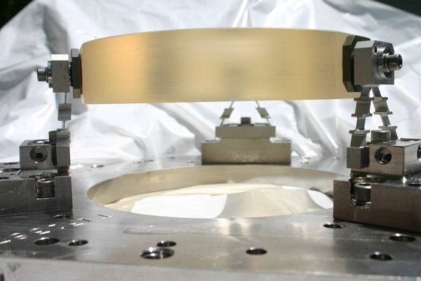
The solution most professionals use for mid-size mirrors is to mount the mirror using beams which are weak in bending but strong in compression. They also try to place the mounting points at the mirror’s neutral axis. The neutral axis is the imaginary surface inside the mirror blank itself which, if the mirror is bent in any way, bends, but neither compresses nor stretches.
An example of this kind of mount is shown in the following photograph of the system used to mount the Zerodur primary mirror in the Cassegrain telescope used in the Deep Impact mission to Comet Tempel 1. You can see that the mirror supports connect to the mirror at the mirror’s neutral axis, the metal mounts are glued to flats ground on the side of the mirror, and the supports are angled to prevent rotation or tilt. They are also cut away so that they act as if they had pivot points at either end, while still retaining the axial stiffness of a rigid beam. These particular beams have been wire EDM’d to shape, but they could as well have been milled or ground to shape.
At some point, the opto-mechanical technology used in space flight will appear in amateur telescopes, the state of the art will advance, and we’ll all get better stuff, including a direct return on our tax dollars. Life can be very good.