I took delivery of my 20” Obsession (#369: all Obsessions have a serial number) in February of 1998. It was my last big splurge before my oldest was due to go to college, soon to be followed by her sister. Back then it was a plain unpowered system, about what I could afford at the time. I hadn’t even invested in any good eyepieces. I soon realized that the cheap Kellner’s I used in my venerable Coulter Odyssey 1 (13.1”) were not even close to taking advantage of the scopes’ capabilities. TeleVue hand grenades were the first upgrade. Over the years and after attending numerous national star parties and seeing how the truly Obsessed observe, I’ve tended to upgrade my equipment to make observing a more rewarding and convenient hobby.
This time around (Christmas 2006), I was searching for a more elegant and simplified way to route power to the UTA (upper tube assembly). I had learned on the west side of the state that observing in Michigan dictated some type of dew removal system to enjoy more than a little observing on any clear (and humid) night. Typically the controller part of dew removers are installed on the UTA (upper tube assembly: upper left in Figure 1) so attached cords can be easily routed to the eyepiece, finder scope, secondary, etc. I invested in the standard Kendrick Dew Controller (their older, non-microprocessor version). This has a long power cord terminated in a male cigarette-lighter connector intended to be plugged into the power inlet provided on many 12VDC batteries used by amateur astronomers. I typically wrapped the cord around and around the truss poles and down to the front of the mirror box where I had a small 12VDC battery suspended in a wire bracket. This worked for me for years, but the battery did not have great capacity and I didn’t like the aesthetics of cords dangling around the scope, even if they were covered by the telescope shroud.
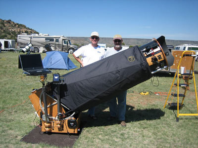
During Obsession Refit #1, I finally upgraded to the ServoCAT Track/GOTO telescope system marketed by Gary Myers, as well as adding a PC support table and DSC “stalk” to hold the Argo-Navis. These add-ons were provided by Charlie Starks of Markless Astronomics (see Figure 2). This brought a whole new dimension to my observing. Firstly, since the scope now tracked objects, I could enjoy the benefits of large aperture and high power and study faint fuzzies under various magnifications without constantly adjusting the moving field of view. Secondly, since I wasn’t getting any younger I wanted to spend less time finding objects (on nights that it was moonless and clear) contained in the Herschel 400 and Herschel II observing lists and spend more time studying them. Lastly, an attached PC let me use SkyTools (sorry Guide fans) to plan my observing session, control the ServoCAT, and then log the object after I had studied it.
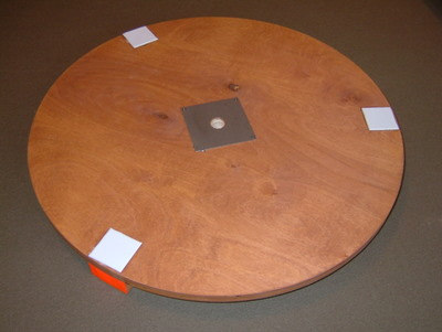
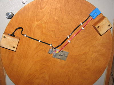
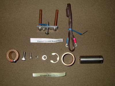
The problem with all this added electronic equipment is the significantly increased demand for more juice from the battery. So, I upgraded capacity to a 115-amp hour deep-cycle marine battery (well, this was meant to last a few nights without recharge) that would plug into the new circular ground board (see Figures 3-5) which replaced the original triangular board. To drive the scope in azimuth, a servo was installed on the inside of the rocker box and a drive gear proPage trudes down through a hole and, when engaged, rotates the rocker box and hence whole telescope around the circumference of the ground board. The fluorescent orange paint on one of the three ground board feet indicates which foot has the power receptacle. The metal plate you see in Figure 3 is the surface for the negative (-) part of the circuit which is wired from beneath (see Figure 4).
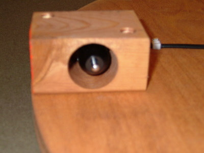
When I am in the field and remote from live AC current, I use the 12VDC plugged into the foot shown on the left in Figure 4, and close up in Figure 5. When I’m observing at a site where AC is available, I utilize a 15VDC power supply and plug into the Anderson Power Pole quick-connector (blue) shown in the upper right of Figure 4. You can also see how the circuit is split on the ground board: negative is transmitted through the board to the plate seen in Figure 3; positive is routed through the central pivot that is also attached to the azimuth encoder. The advantage to this solution is that your telescope can rotate freely without cords becoming entangled since the cord is connected to a stationary ground board.
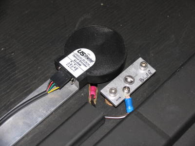
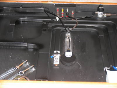
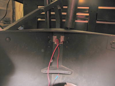
The rocker box holds all the wiring, the power distribution panel, and servo motors and encoders (Figures 6-8). The cylinder shown in Figure 6 is conductive and is attached to the azimuth encoder (Figure 7). The two-pronged metallic piece at the top of Figure 6 is the conductive path for the negative terminal. Two holes are drilled through the rocker box for the spring-loaded contacts, which are in constant contact with the plate shown in Figure 3. The negative path is enabled by an “E” ring clip surrounding the central pivot. This is also spring-loaded to ensure the circuit is maintained.
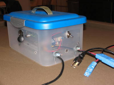
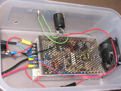
Figures 9 and 10 show the 15VDC power supply in an enclosed plastic box that was obtained from Wal-Mart. I got the idea from Skip Copp at BFSP last year. We utilize 15VDC instead of 12 VDC due to the voltage drop from the power supply to the UTA. I originally used a 12VDC power supply, but with all the gear drawing power, every time the PC hard drive engaged there was a noticeable performance drop in the system. Supplying just a little more voltage through #8AWG wires to the telescope solved that problem. I also attached another cigarette lighter and RCA receptacle to the box to power my 12VDC heated beverage cup for use on those chill nights.
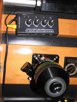
So at this stage, how did I get power to the UTA? The answer was fairly simple if not completely elegant. I ran an extension from the power panel to the inside front of the rocker box. I then drilled the box and attached an RCA plug on the outside. For the truss tube carrying power, I attached two RCA plugs at either end of the tube and ran wire through the inside of the tube to carry the (+) path. The truss tube itself, being aluminum, carried the (-) path. This then needed a flexible patch cable to connect the truss tube with the connector in the rocker box. More connections—more power loss. This circuit was fused to prevent cross polarity and protect the dew controller in event of an electrical short. Oh — did I neglect to mention that I initially forgot to fuse protect this circuit? Down at WSP 2005 one dewy night led to some type of short that completely fried the Kendrick dew controller. Silly $100 mistake since I then “upgraded” to a 1000 Oaks dew controller.
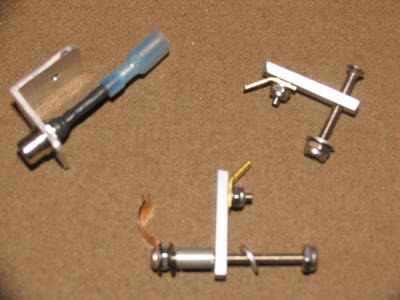
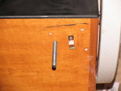
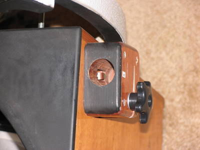
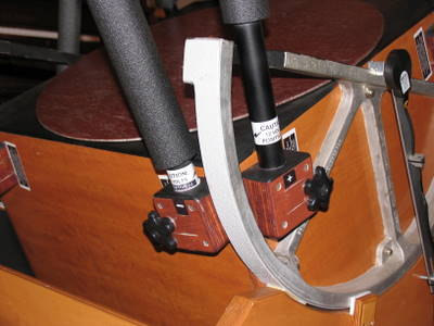
I was fairly content with this setup for a year or so, but still didn’t like the patch cord down below with its potential to bind during an altitude slew. So I was pleasantly surprised to hear from Charlie Starks that he had solved the problem in a completely elegant way—utilize two truss tubes, one for (+), one for (-) and make it “plug and play.” See figures 11-14. A copper-beryllium strip was designed to take advantage of a natural cavity the Dave Kriege had designed into his truss tube blocks. Charlie devised a template to drill through the mirror box, insert the terminals, and reattach the block. That left a connector much like used in a battery powered flashlight. Merely inserting the truss tube automagically provides a path for the circuit, no exposed wires anywhere.
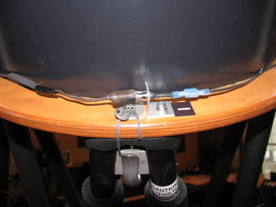
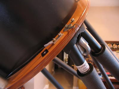
The pole seats on the UTA were drilled through with a conductive bolt and a terminal attached on the top side of the lower UTA ring (see Figures 16-18). This of course means that two poles carry each charge. The (+) pole is opposite the eyepiece and it travels 90° around the UTA and joins with the (-) pole. An RCA plug then provides a terminal for the highly shortened Thousand Oaks controller. Yes, this system has an inline fuse down in the rocker box to prevent circuit overloads.
With this system and ~13.8 VDC supplied to the telescope, there is never any shortage of power with the PC humming along and the ServoCAT, dew heater, mirror fan, and ArgoNavis all drawing at the same time.