Ask most any amateur astronomer “How many telescopes is enough?” and you’ll probably see staring back at you a confused face as if to say “Enough telescopes? There’s no such thing as having ‘enough’ telescopes!” To the telescope junkie that many of us are, scopes are so varied in purpose, capability, and price, that no matter how many you already own there’s always yet another one that you need to fill a particular niche. This is particularly true for anyone who makes their own telescopes. Long before one scope is finished, the maker is already formulating plans in his head for the next project. After all, one can’t call himself a telescope maker if he’s not making telescopes! And so it is with me. Long before I finished my 8-inch f/8 “Mars Scope” (so-named because I built it primarily for the great Mars opposition of 2003), I was making plans to build “Smurfette”—a six-inch f/4.5 rich field telescope, also known as an RFT.
An RFT is so-named because its primary purpose is to provide low magnification, wide field views. The wide field of view is ideal for viewing the rich star fields of the Milky Way, hence the name. They are usually of modest aperture, around six or eight inches, and with relatively fast focal ratios, typically between f/4 and f/5. This usually yields a real field of view (FOV) of anywhere between one and a half and three degrees.
My 13.1 inch Dob has a focal ratio of f/4.5, but its large aperture puts its biggest FOV at under a degree. So does the Mars Scope, due to its slow, f/8 speed. I needed something to provide a larger field for those larger, chunkier, deep sky objects, or comets, or just for cruising the Milky Way. The largest FOV of this new scope would be over two degrees, which is just what I was looking for.
Just like the Mars Scope, Smurfette would be the re-incarnation of a scope I had built long ago. Its primary mirror was the second Newtonian mirror I ever made, or more precisely it was a re-grind of my first mirror. Working alone in my garage in 1969 I was never able to grind that first six inch mirror down to an f/8 curve, so it ended up at f/9. It was probably no better than half-wave, and it never performed particularly well, so after a couple years I replaced it with a commercial f/8. After figuring out what I was doing wrong I re-ground that original f/9 mirror to a fast f/4.5. That mirror was quite a bit better than my first, and I enjoyed the scope for a few years until I lost interest in astronomy during my college years. Then came the Dobsonian Revolution in the early 1980s, which re-kindled my interest in astronomy. To make a long story short, first came the 13.1 inch Dob, then the first incarnation of the Mars Scope, then the successful refigure of the 13.1 inch mirror, then several failed attempts to refigure the eight inch mirror, then similar failed attempts to refigure the RFT mirror, and then finally success with the eight inch in 2003. Whew! It was my success with the eight inch that convinced me that I should make a final attempt to re-do the six inch. And in the winter and spring of 2005-2006 I did just that.
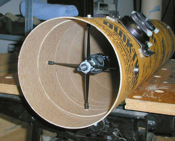
I started with the optical tube assembly (OTA) before working on the primary mirror so that I would have something in which to star test it uncoated before shipping it off to be aluminized. The stubby tube of an RFT, due to the relatively short focal length, puts less severe demands on the rigidity of the tube, so I felt comfortable using a 7.375” ID Quik-Tube, the kind you find at Lowe’s and Home Depot. It’s a thin walled tube, only about one eighth of an inch, which made me a little worried that it might not stand up to the tension of the spider vanes. So I cut a strip of spare tubing 3” wide, and cut a slot out of it so that it was a snug fit inside the tube. I glued it in place using water-resistant Titebond II carpenter’s wood glue so that it was centered where the spider mounting holes would be. That made the tube much stiffer there making it more than strong enough to support the spider. Next I drilled holes for the focuser and spider. I positioned the focuser hole my personal rule-of-thumb one tube diameter from the front of the tube, which provides dew protection for the secondary mirror and helps keep stray light out of the light path. Lastly I drilled holes for the primary mirror cell, and mounted the focuser, spider and secondary mirror. I now had a test bed for star testing, so I set it aside and moved on to refiguring the primary mirror.
Refiguring the primary mirror proved to be a fairly straightforward process. Despite or even because of the previous failed refiguring attempts the mirror was well polished out, so all that was left to do (albeit the most difficult part) was to figure it. In other words, to convert the mirror’s shape, or “figure”, to that of a paraboloid.
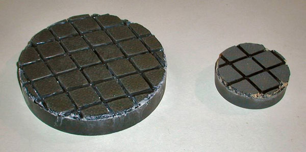
A paraboloid is the surface you get by spinning a parabola around its axis, and the process of changing a mirror’s surface into a paraboloid is called parabolizing. The surface of a Newtonian reflector’s primary mirror must be in the shape of a paraboloid (or very nearly so) to form sharp, usable images. Now because the desired surface is aspherical, you cannot polish the mirror on a rigid surface. The polisher must be viscous and “flow”, or change shape, as the mirror’s changing shape passes back and forth over it. For this reason the mirror is polished on what is called a pitch lap. For almost all amateur-made optics the polishing lap is simply the glass grinding tool covered with a channeled layer of pitch.
I had some problems with the pitch I was using being too hard, but after solving that problem getting the mirror nearly spherical before parabolizing was pretty easy. Note that I said “nearly” spherical. In slower mirrors, you want to get as good a sphere as possible before parabolizing because the difference between a sphere and the desired paraboloid is very small, and any zonal irregularities will still be present after you’re done. But in a fast, f/4.5 mirror, there is a lot of glass to be removed, and any minor zonal defects will all but disappear by the time you are done. It only took a handful of polishing sessions over the course of a couple weeks of spare evenings using the full size lap to get it ready to parabolize.
For whatever reason, I’ve never had any real success parabolizing using the classic method with a full-size lap, so I used the half-size lap method that Tom Ryan taught me when I made the mirror for the Mars Scope. That method worked exceptionally well with that scope’s eight inch mirror and I had equally good results with the six. It just seems to give you a nice, smooth paraboloid every time nearly automatically.
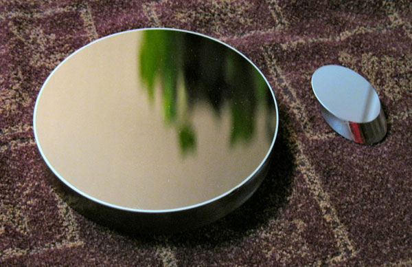
After a total of a month and a half’s worth of work in my spare time (again taking over my wife Debi’s kitchen, which she so graciously tolerated), my Foucault test results said I was done—one eighth wave at the wavefront or better. This is as good as I had hoped for, considering the fact that there is little margin for error with fast paraboloids. But before I declared the primary finished I wanted to star test it uncoated first. On the night of March 22 I put the bare mirror in the raw OTA, bungee corded it to the Mars Scope’s mount, and looked at Polaris and Regulus. The two were surprisingly bright (remember the mirror was uncoated) and they both showed very nice, nearly textbook diffraction patterns at 274x. I also looked at Saturn and Jupiter and they looked very nice, too, although quite dim. I thought I was getting a hint of Cassini’s division, but I could easily see Saturn’s shadow on the far side of the rings. And Jupiter’s main belts were easy. Okay, now I can call it done!
The next day I shipped the mirror and matching 1.52” minor axis secondary mirror that I had on hand from the original version of the scope to Spectrum Coatings in Florida, to have them apply enhanced aluminum coatings on both mirrors. When I got them back about eight weeks later, boy, did they look purdy!
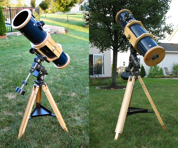
After finishing the mirror, I returned to the OTA. To make the tube dewresistant I sealed the inside with a couple coats of shellac, and coated the outside with a couple coats of navy blue Krylon polyurethane enamel, the same paint as is on my 13.1 inch Dob. To make the inside of the tube really soak up any stray light, I lined the entire interior of the tube using some black, velvet-like flocking material that I obtained from McMaster-Carr. Man, is that stuff black! Even at grazing angles of attack, as is the case for light entering a Newtonian telescope tube, there is almost no reflection at all. Black flocking is far superior to flat black paint—keep that in mind if you ever build your own scope or decide to improve one.
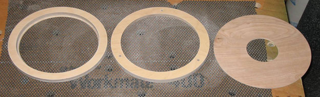
Next I needed to make reinforcing trim rings to protect and support the ends of the tube. Fortunately for me, Nathan Murphy was at that time cleaning out his garage in preparation for moving to New York. He generously gave me a bunch of scrap pieces of very nice 13-ply, three-quarter inch, Finnish birch plywood. Very nice stuff—not only are the veneers hardwood birch, but so are all the intermediate plies. Very dense (read heavy), strong, and stiff. It was even pre-finished on both sides! I used it for the reinforcing tube end rings and for other wood parts for the mount. I cut all the circular plywood parts using a router attached to a circle cutting jig.
The primary mirror cell is from University Optics, the spider and secondary holder are from Kenneth Novak (God rest his soul), the focuser is the old helical I had on the 13.1 inch for so many years, and the finder is a Rigel Quickfinder. For rapid cooldown, a three inch computer fan is mounted to a piece of one quarter inch birch veneer plywood that attaches to the back trim ring using Velcro fasteners. The Velcro attachment made the fan plate easily removable for access to the primary cell’s collimation screws, and also provides some isolation of any fan vibration from the rest of the scope. And of course all mounting screws and other hardware are stainless steel, for the obvious reason that here in Michigan the scope will be exposed to lots of dew. Also for good moisture resistance, I used a couple coats of Minwax oil based clear spar (marine) polyurethane to finish all the wood parts. Three threaded inserts in the front face of the front trim ring allow for securing a solar filter.
Before I started the project I knew that I wanted a driven, equatorial mount for this scope, so I was on the lookout for one. Again it was Nathan Murphy to the rescue. As luck would have it he had a Vixen Great Polaris mount for sale. (Now there’s a surprise—Nathan selling used astro equipment!) The price was right, so money changed hands, and his loss was my gain. It’s a very nice mount, with very smooth motions and a single axis RA drive.
I had to build a cradle for it, so I patterned it after the cradle I made for the Mars Scope. It features the same hinged clamshell design, and also like the larger version it’s simply glued together using water-resistant carpenter’s wood glue and biscuits. The biscuits make for a strong joint but without any visible screws or fasteners. It bolts onto the mount’s dovetail bar for easy attachment and removal to and from the mount head.
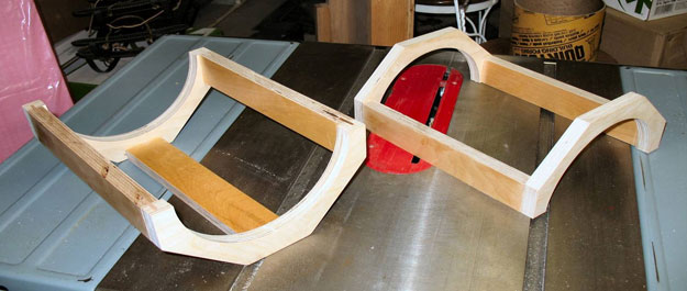
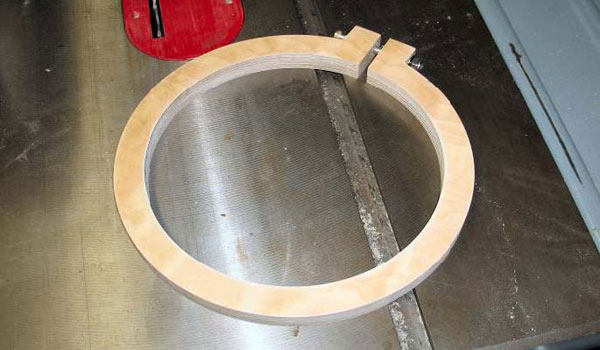
Now if you’ve ever used a Newtonian on an equatorial mount, then you know that the eyepiece can very quickly end up in some weird, unusable orientations. The cradle must allow for rotation of the tube. The problem is that when you loosen the cradle to rotate the tube, it is difficult to keep the tube in the same location fore and aft in the cradle. Failure to keep it so will result in an out-of-balance condition where the scope won’t stay put when you let go of it. My solution was to make a clamp ring out of the same Finnish plywood, and once I determined the correct balance point I clamped it onto the tube just above the cradle. It keeps the tube from sliding through the cradle when I loosen it, and keeps it in the same location every time. Moreover, if I ever make modifications to the scope, or say add a camera, I can loosen the ring and re-clamp it in a new position.
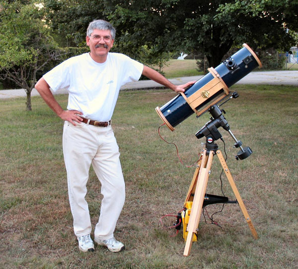
By now you may be wondering to yourself where I came up with the name “Smurfette” for this scope. Well, I usually don’t name my scopes, but I was in conversation with Mark Deprest pretty much from the beginning of the project, and at that same time Mark was building his own new eight inch scope. He would refer to it as “Gilda”, and in fact I believe he has names for all his scopes. He would ask me what would I name mine, so I started thinking about it. After a while it came to me. In many respects this scope is just a shrunk-down version of my 13.1-inch Dobsonian. They’re both f/4.5, and they both would be the same navy blue. One big, one small. Both would be blue. Hmmm... big, little, blue. Then it hit me—Smurfs! I’ve always enjoyed watching those little blue rascals. The big scope would be named after Papa Smurf, and the little one would be named after that cute, little Smurfette!
So how does she perform? Pretty well, even if I say so myself. The wide field of view provides gorgeous, low-power views of the summer Milky Way. With an OIII filter and my lowest-power eyepiece (24x) the North America nebula fills the entire field! Other large objects such as the Andromeda galaxy, the Double Cluster, and the Veil nebula are beautiful as well. It works well at high magnifications too. Both Saturn and Jupiter are very crisp and clean. On one night I was even able to see two or maybe three of the elusive, tiny craterlets in the floor of the Moon’s crater Plato.
One thing I found was that at high power the scope was a little shaky. So I replaced the extruded aluminum tripod legs with homemade legs using some of that same Finnish plywood. Not only are they good and solid, but they look real nice and the wood matches and complements the other wood parts on the scope. It still shakes a little at high power, though, but because it’s normally going to be used at low to medium magnifications, I can tolerate it. I may try a set of antivibration pads for the leg tips to see if they help.
There will probably be some tweaks here and there, but by and large Smurfette is done. Which means that if I am to keep calling myself a telescope maker, then I had better get busy and get another one in the works. But then again I must have been thinking that all along, right?
Stay tuned.