Chapter 11: Nonisothermal Reactor Design: The Steady State Energy Balance and Adiabatic PFR Applications
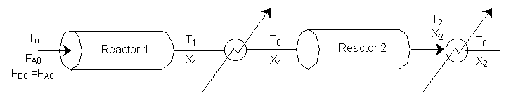
Interstage Cooling
Elementary Exothermic Reversible Reaction:
\( A + B \rightarrow 2C \)
\(-r_A' = k [C_A C_B - \frac{C_C^2}{K_C}]\)
At equilibrium:
\(-r_A' = 0 \Rightarrow K_C = \frac{C_Ce^2}{C_Ae C_Be}\)
We can stage the reactors using either the overall conversion X (easiest way) or the conversion per reactor X¢.
\( X = \frac{\text{total moles A reacted up to a point}}{\text{mole fed to first reactor}} \)
\([C_A = C_{A0}(1-X) \cdot y \cdot \frac{T_0}{T}], \, [C_B = C_{A0}(1-X) \cdot y \cdot \frac{T_0}{T}], \, [C_C = C_{A0}(0 + 2X) \cdot y \cdot \frac{T_0}{T}]\)
\( K_C = \frac{4X_e^2}{(1-X_e)^2} = K(T_2) \cdot \exp\left[ -\frac{\Delta H_{Rx}}{R} \left( \frac{1}{T_2} - \frac{1}{T_1} \right) \right] \)
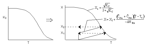
Adiabatic Energy Balance
\( X = \frac{\sum \theta_i \hat{C}_{p_i} (T - T_0)}{-\Delta H_{Rx}} = \frac{(C_{pA} + C_{pB}) (T - T_0)}{-\Delta H_{Rx}} \)
The following is an exercise for the more curious and is not necessary to study if you are pressed for time. What follows is in response to a question asked by Adarsh Radadia, a student in the undergraduate reaction engineering class of Winter 2001. Adarsh wanted to know why we didn’t include the reaction products in the balance to the second reactor. The answer is (as shown below) that there are two ways to work the problem. One method (shown above) is to use the overall conversion which is the easiest way to work the problem, and the other method (which follows) is to use the conversion for each reactor. In the case of using conversion for each reactor you include the reaction product from the first reactor as shown below in the answer to Adarsh’s question.
(2) Based on feed to second reactor
\( X' = \frac{\text{moles A reacted in second reactor}}{\text{mole A fed to second reactor}} \)

\( C_A = C_{A0}(1 - X') \left( \frac{yT_0}{T} \right) \)
\( C_B = C_{A0}(1 - X') \left( \frac{yT_0}{T} \right) \)
\( C_{A01} = \frac{F_{A1}}{v_0} = \frac{F_{A0}(1 - X_1)}{v_0} = C_{A0}(1 - X_1) \)
\( C_C = C_{A0}( \theta_c + 2X' ) \left( \frac{T_0}{T} \right), \theta_c = \frac{E_{C01}}{F_{A01}} = \frac{2F_{A0}X_1}{F_{A0}(1 - X_1)} = \frac{2X_1}{(1 - X_1)} \)
\( K_C = \frac{(\theta_c + 2X')^2}{(1 - X_e)^2} \)
\( \sqrt{K_C} = \frac{\theta_c + 2X'}{1 - X_e} \)
\( \sqrt{K_C} - \sqrt{K_C} X_e - \theta_c = X_e \)
\( \frac{\sqrt{K_C} - \theta_c}{2 + \sqrt{K_C}} = X_e' \)
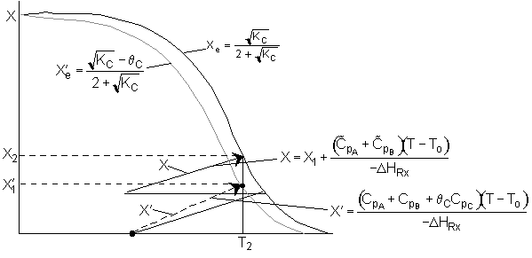
\( X' = \frac{\sum \theta_i C_{p_i} (T - T_0)}{-\Delta H_{Rx}} \)
\( X' = \frac{\left( \tilde{C}_{pA} + \tilde{C}_{pB} + \theta_c \tilde{C}_{pc} \right) (T - T_0)}{-\Delta H_{Rx}} \)
We see which ever conversion we use, X or X¢, we obtain the same temperature and overall conversion exiting the second reactor.
\( X_2 = \frac{F_{A0} - F_{A2}}{F_{A0}} = \frac{F_{A0} - F_{A0} (1 - X_1)}{F_{A0}} = \frac{F_{A0} - F_{A0} (1 - X_1) (1 - X_1)}{F_{A0}} \)
\( X_2 = 1 - (1 - X_1)(1 - X_1) \)