| Strength Demands and Capacities (Get a grip on it!) T. Armstrong, U of Michigan |
1.0 Introduction
This chapter describes basic procedures for determining and comparing task strength requirements/demands and human strength capacities. Requirements refer to minimum forces and moments that must be exerted at a given location in a workspace to complete a task. Forces and moments are vectors and include both magnitudes and directions. “Demands” refer to the corresponding loads imposed on the body to complete that task. Either term may be used depending on your perspective.
It seems obvious that task strength requirements should not exceed the strength of persons or populations who perform those tasks. Yet time again and again we find equipment and tasks designed in ways that that exceed the capacities of many people. The result is a reduction in the number of qualified workers or in the number of people who might buy and use that equipment. Additionally repeated or sustained forceful exertions can result in fatigue that impairs performance and in chronic musculoskeletal injury and disability. Aside from the costs to manufacturers, employers, workers, and consumers, failure to consider task strength requirements can result in legal action, e.g., ADA, OSHA, workers' compensation, and product liability.
The following concepts provide a framework for discussion of strength demands and strength capacities.
- Task strength requirements (demands): The forces and moments (torques) required to maintain control of a work object at a location in space.
- Worker strength requirements (demands): The forces and moments (torques) that are produced on or about each joint of their body to maintain control of a work object and of their body at a location in space.
- Worker strength capacity: The maximum force or movement (torque) that a person or a population can exert at each joint of their body to maintain control of a work object and of their body at a location in space.
- This chapter focuses mostly on the hand, but the underlying concepts are applicable to other parts of the body
2. Strength requirements/demands and capacities
- "Task strength requirements"refer to the forces and moments that are continuously required to control the position of work objects irrespective of who is performing the task.
- Task force and moments are related to the weight of the object, internal or external reaction forces, drag, and acceleration/deceleration. These forces and moments can be affectd by:
- Maintenance of equpment, e.g, tool bits, blade sharness, machine maintenance, adjustment and use of mechanical assist
- Quality control. Parts that don't fit well or consistently may require extra force to be engaged or assembled.
Worker strength requirements (demands)
- "Worker strength demands" refer to the forces or moments that must be produced about each joint of the body to position the body and to gain and maintain control of a worker object for a given task.
- Joint loads are usually expressed as moments (inch-pounds, newton-meters, etc.). In some cases they may be expressed as a push or pull force (pounds, Kgf, Newtons) for a given posture or location. Prehensile hand forces are typically expressed as forces.
- Work object location affects how workers position their body.
- Posture determines the spatial relationship between joints and external forces directly affects joint loads and must be considered. Unless they are constrained by task and equipment factors, workers will typcially find a position of maximum strength to perform a given task.
- Body size and weight affect body posture. Body weight can increase strength required to support the body, but in other cases it can decrease the muscle forces required for downward forces. Body weight can affect how close a person can get to a work object and increase reaching.
- visability can affect how workers position their bodies to see around something or to avoid glare.
- Wearing protective equipment can affect body position. For example gloves can increase friction, but also can interfer with grip.
- Lighting, vibration, moisture
- In addition to task requirments, worker strength requirements are affected by the size, weight, body proportions, body position, and garments of the worker and by the method that the worker uses to perform the task
- Individual work methods affect how a worker positions and moves their body to perform a tasks and the resulting forces
- Holding a phone or tablet
- Holding a knife
- Wiggling a knife or connector
Worker strength capacity
- Srength capacities refer to the amount of force or momement that a given person or population can produce for a given posture under given conditions.
- Torques or forces?
- Describing hand strength Demands
- Absolute force (pounds, Kgf, Newtons) or moment (inch-pounds, N-m) vectors
- Percent capable- Fraction of percentage of selected population strength
- Relative force: Percent of Maximum voluntary contraction, %mvc, or Percent of Maximum exertion, %ME = [(strength required) / (strength)] × 100%
Estimating hand strength requirements
- This subject is discussed hin Section 2. A basic exzmaple is discussed here to demonstrate the above concepts.
- Examine the external forces and moments acting on the work object
- where it is exerted on the body, 3) posture, 4) action
- Examples (Fig 1):
- Holiding a 50 pound tool box
- Holding a knife
- Holding a screwdriver
- Holding a tray
- Grasping a railing
- Holding a phone
- Holding a tablet
- Strength demands are often expressed as a percentile. This provides and idea of what percentage of the population should be able to perfor the task -- although this will require a maximum or near maximum effort for many.
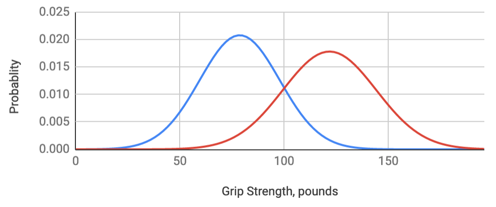
- These calculations usually are based on the assumption that human strength is a normal distribution. This is not totally correct. Strengths are generally skewed towards higher strength values. Still, calculations base on a nromal distribution provide a useful approximation.
- Percentile calculation:
- Determine the strength average and standard deviation for the population of interest. (see links to published studies below: 4.3 Published hand strength data)
- Calculate: z = (FDemand-Faverage)/Standard Deviation
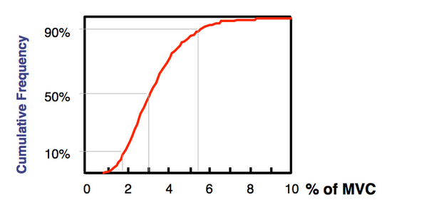
- Look up percentile (cumulative probability, α) for the calcuated z value (Table 1)
- These These last two steps can be performed using the information or calculator in Fig 2.
- Start with female strength. Most males should have sufficient strenth capacitiy of the required strength is less than the average female value.
- The right-hand strength for 30-39 year females (Strength is usually greatest in this age range). Strength estimates can then be adjusted up or down based on other considerations.
- See links to published studies below: 4.3 Published hand strength data
- 30-39 year old right-hand female strength: 340±69.6N (78.7±19.2 pounds)
- Calculate standard normal:
- z = (FDemand-Faverage)/Standard Deviation
- z= (200-340)/69.6 = -2.01149425287
- from Fig 2 it can be seen that over 95% of Females should have sufficient hand strength to "briefly: hold the tool box.
- It can be seen that most females should be able to hold the tool box, but those on the lower end of the strength range (Fig 2b)
will be exerting nearly 100% of their maximum strength. They will
- only to be able to hold it for a short time
- have only a small safety margin to resist the inertia during lifting or other force perturbations.
- Hand strengths are typically based on maximum finger, grip or pinch force.
- %MVC or %ME = Exertion force or moment / Strength *100% (Also may be expressed as a fraction of maximum or on a scale from 0 to 10)
- %MVC = 50 pounds / 78.7 pounds x 100% = 64%.
- 64%MVC can be maintained for only about 60s with significant discomfort.
- Determine estimate how long someone with average female strength could maintain this exertions. see: Localized Fatigue

(a)
(b)
(c)
(d)
(e)
Percent capable (the lower percentiles)
Results

Percentile Calculator, Enter:
Percentile
z1%
-2.3262.5%
-1.965%
-1.64510%
-1.28225%
-0.67550%
075%
0.67590%
1.28295%
1.64597.5%
1.9699%
2.326
Strength demands are often expressed as a percentage of the maximum force or moment that can be exerted by the body part of interest.
%MVC = / × 100% =
Example: Determine the percent maximum voluntary contraction, %MVC, for someone with average female grip strength to hold the toolbox as shown in Fig 2a:
3. Determining strength requirements
3.1 Worker ratings
Worker ratings refer to estimates of effort provided by workers peforming the task of interest. They are subjective and ratings may vary significantly among persons performing the same task. These diffences may be due to strength differences, experience/training, personal tastes, and other factors. Even though subjective methods are inherently subjective, steps can be taking to make them "more" objective. On of the most important thin that can be done is to provide bench marks, e.g., 0 is no force or effort and 10 is the greatest exertion possible. Zero and 10 are most commonly used to define the upper limits. When these ratings are applied to specific exertions they nominally correspond to exertions of 0 to 100%MVC. The specificity and consistency of the ratings are very sensitive to how the the investigator frames and words the question. Where and when possible, it is desirable to as multiple workers to rate the same tasks or exertions, but often only a small number or even one worker doing a given job.
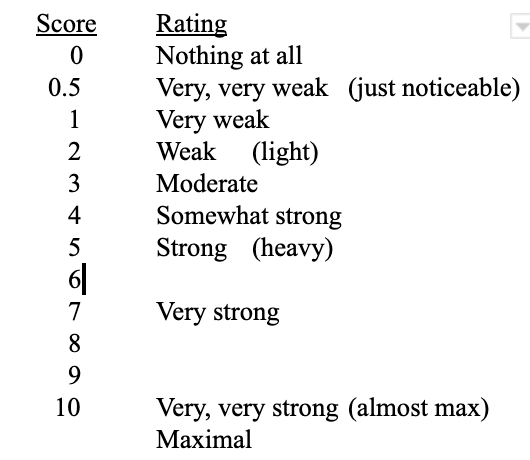
3.1.1 Verbal ratings 0-10
Verbal ratings can be as simple as asking a worker to rate the effort to complete a given action. Most people are familiar with the use of 0 to 10 scales to rate used cars, cutomer satisfaction, pain at the doctors office, etc. and have no trouble and understaning and applying the concept.
- The worker/user is asked "Rate the force/effort to perform a specified step of a task on a scale of 0 to 10 where 0 is no force and 10 is the greatest that you can imagine."
- The question should focus on a specific too, part or body part, e.g. hand elbow, shoulder, etc.
- Performing a maximum exertion in the same way that the task is performed can increase the accuracy of verbal ratings.
Examples:
- "Please rate the force to join those connectors on a scale of 0 to 10 where 0 is no force and 10 is the greatest that you can imagine."
- "Please rate the force to trim this branch with these loppers on a scale of 0 to 10 where 0 is no force and 10 is the greatest that you can imagine. Fig 3a and 3b."
 Fig 3a: Simple pivot action (fiskars.com) |
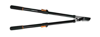 Fig 3b: Extended handles with compounded linkage to amplify hand force (fiskars.com) |
3.1.2 Visual analogue scale (anchor points ⚓)
A visual analogue scale or "VAS" helps improve the consistency of ratings among different (peopleKoppelaar and Wells 2005). Each subject is presented with the same instrument and indicates their rating the same way. VASs are widely used to assess discomfort and effort.
- The VAS is 10cm horizontal line with verbal anchor points at each end describing extremes (additional anchor points may be used).
- User/worker indicates perceived force by drawing a vertical line through the scale.
- The score is determined by measuring the distance between lowest extreme and vertical line in centimeters.
- See Fig 4.
- Precision can be improved if subjects exert maximum force in same position as that used for the task being studied (Marshal et al. 2004).
 a |
 b |
3.1.3 Borg RPE scale
A Borg scale is a series of verbal a linear series of ratings are are arranged on a geometric scale as shown in Fig 5 (Borg 1982). The scale is based on psychophsyical studies that show that perception of a physical stymulus increases on log or a log-log scale. In other words the a doubling of the stymulus is perceived as an increase of one unit of perception. While the underlying theory is supported by sound science, the Borg and VAS scales produce similar results for percieved exertions Ulin et al. (1990).
 |
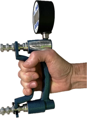
This method is similar to the other subject ratings, except instead of providing a verbal or written rating the subject indicates their perception of the force by an equivelant amount of fore on a force gauge (Bao and Siverstein 2005; Marshall et al. 2004).
The device used to demonstrate force must be matched to task being studied. That is, if the task involves gripping, then the subject should demonstrate their estmate of force using a grip dynamometer. If the task involves pinching, the subject should demonstrate their estimate on a pinch dynomometer. (see Fig 6)
 |
 |
| (a) | (b) |
- Visual analogue scales -- similar to that used for worker self ratings
Also, observers may simply rate on scale of 0 to 10 (see Ebersole et al. 2006) - Experience/training necessary
- Benchmarks or anchor points ⚓ can improve consistency
- Individual v. group ratings
- see: Ebersole ML, Armstrong TJ. Analysis of an observational rating scale for repetition, posture, and force in selected manufacturing settings. Human factors. 2006 Sep;48(3):487-98.
3.3 Instrumentation
Instrumental methods can be categorized as direct or indirect.-
Direct force measurements are divided into two categories
- Measurement of a resultant force.
- Measurement of force distribution patterns.
- Indirect force measurement uses electrical potentials produced on the skin over contracting muscles (surface-electromyography or sEMG) to estimate hand force. This system requires careful selection of the involved muscles and calibration of the sEMG-hand force relationship for each posture for each subject. sEMG signals may be subject to significant variations from movements and other unknown factors.
- Examples of these methods are shown in Fig 7.
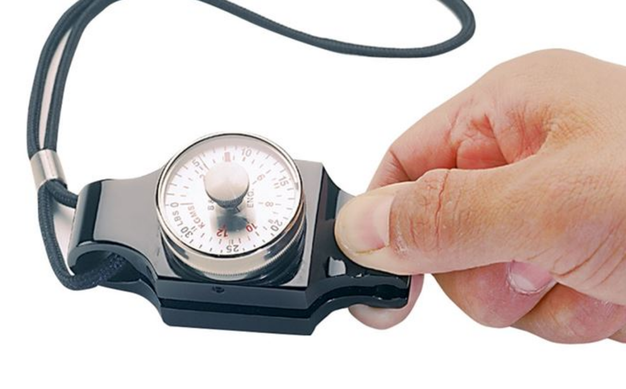
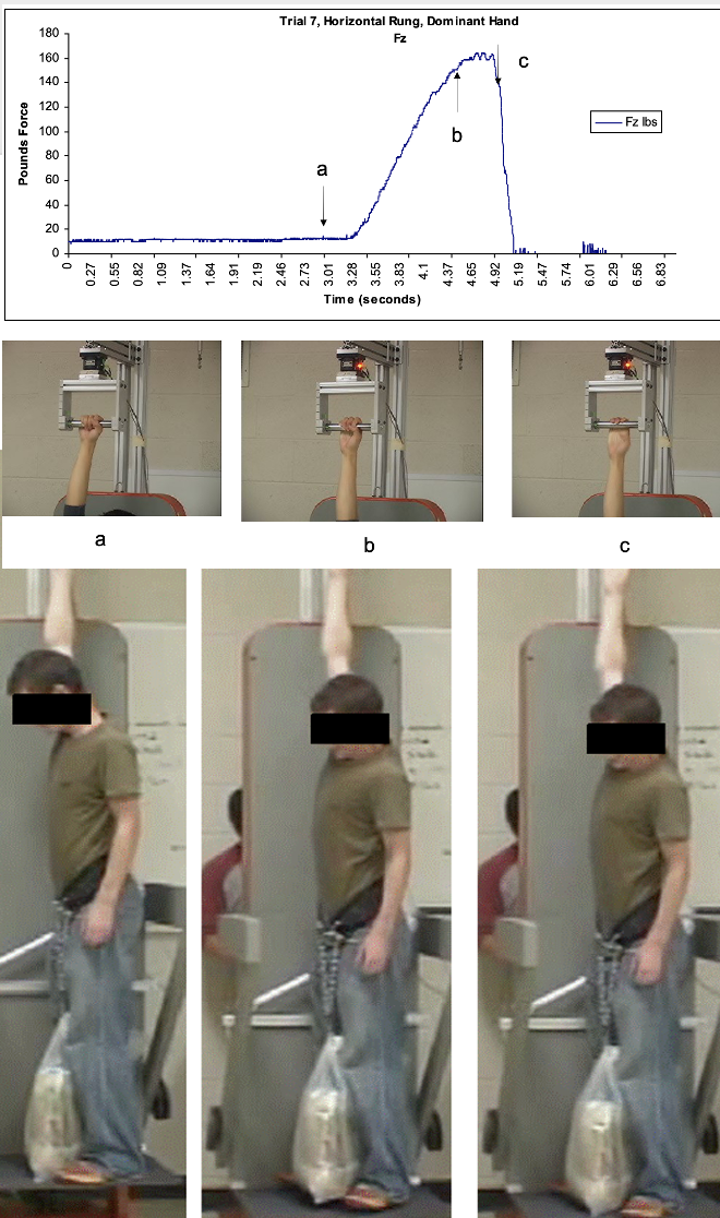
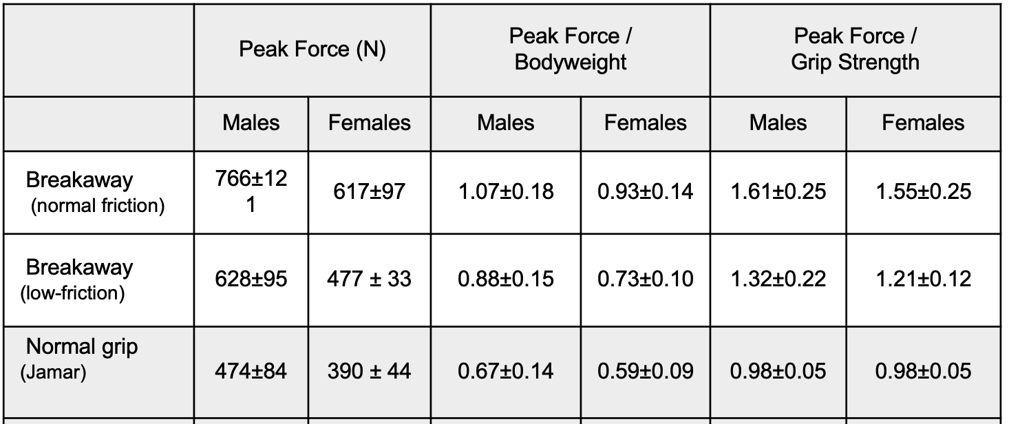
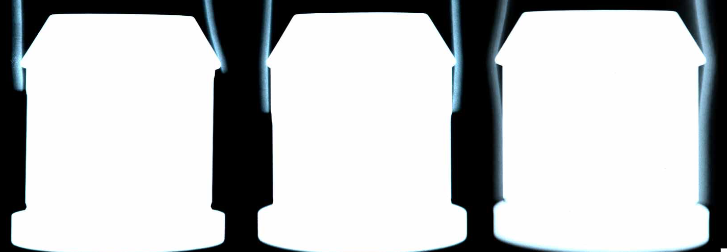
- Fig 7a shows the equipment used for determining the breakaway force (Young et al. 2012). The force on the handle is recorded as the platform is lowered and the worker's weight is transferred to the handle. Breakaway forces are expressed as Newtons and ratios of grip force to body weight and grip strength. Results for low- and high-friction hands show that friction significantly increases the breakaway force.
- Fig 7b shows a cylindrical handle covered with an array of force transducers to measure the contact forces between the hand and the handle. The resultant forces in any given direction can then be integrated the force components aligned with the direction of interest (Seo 2007). Present technology only works well on surfaces with 0 or 1 direction of curvature.
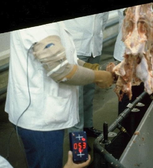
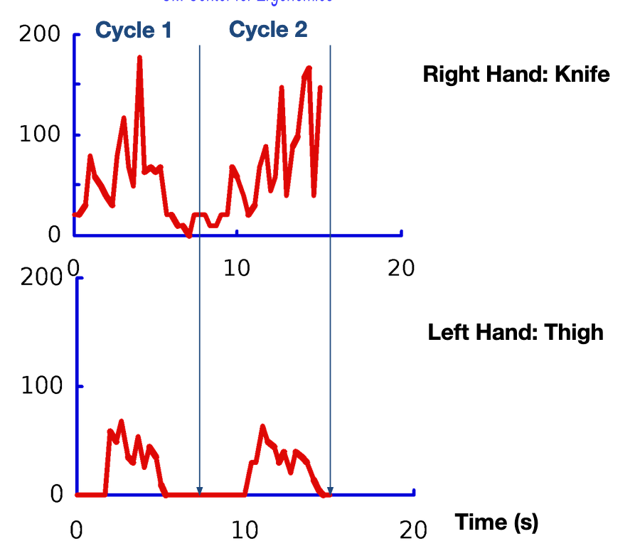
- Fig 7c shows the use of electrical activity, sEMG, of finger flexor muscles in the forearm to estimate the forces exerted with the hands to bone turkey thighs. SEMG signals are displayed and recorded with images of hand and work objects.. Electrical signals are captured from electrodes mounted over the finger flexor muscles in the forearm, amplified, displayed, and recorded in film recordings of the worker at 3 frames per second. Sample results are shown for the right hand holding the knife and the left hand holding the thigh (Armstrong et al. 1982). Careful consideration and some trail and error is necessary to find the optimal electrode locations (Takala, Toivonen R 2023)
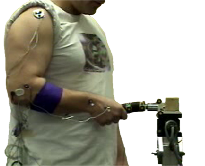
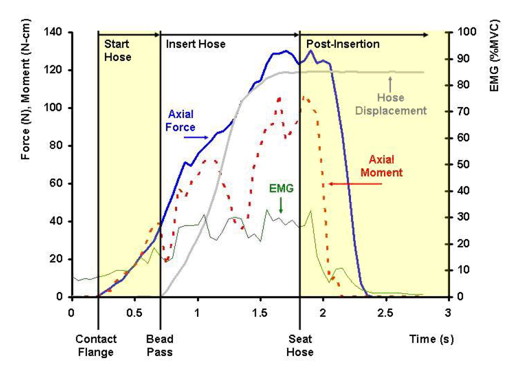
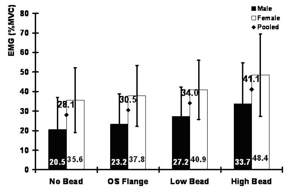
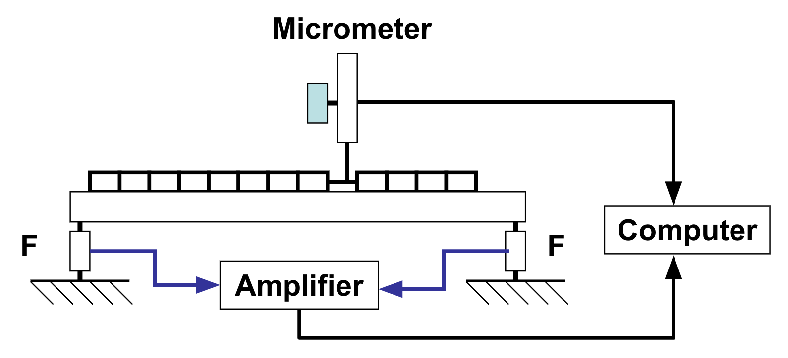
- In Fig 7d, a flange is mounted on a 6-axis force gauge to record the force required to insert a hose onto the flange. At the same time, sEMG signals recordings from electrodes placed over the finger flexor muscles in the forearm for estimating grip forces. The resulting force patterns are shown for selected combinations of inside hose diameters and outside flange diameters. (Griesbaber et al. 2007)
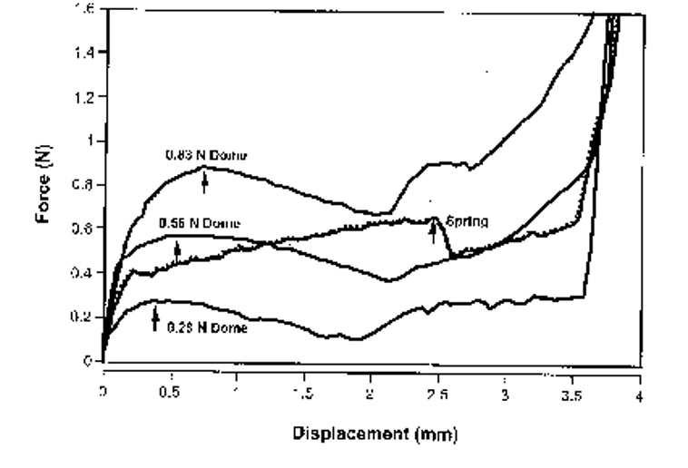
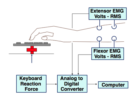
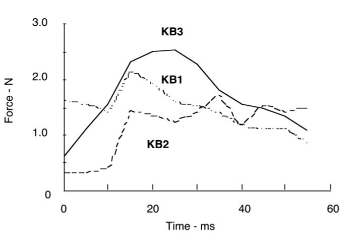
- Fig 7e shows a keyboard force-displacement curve. The required keyboad force is determined as the the local maximum which correspondes to activation of the keyboard or "make force." Sample results are shown for keyboards with key actions (Armstrong et al 1994; Gerard et al. 1996).
- The workforce requirements correspond to the force exerted by the user which is typcially 2.5 to 3.9 times the make force. (Armstrong et al 1994; Gerard et al. 1996).
  a 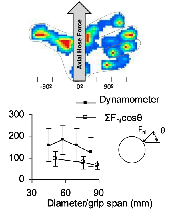 b |
  c |
    d |
  e |
   f |
3.4 Biomechanical analysis of task hand force demands
- Basic laws of physics tell us:
- the sum of all forces and moments acting on a static object or an object moving at a constant velocity must add up to zero.
- for every force, there is an opposite and equal reaction force.
- The following examples illustrate how these laws can be applied to estimate required hand forces for various work objects and conditions.
- Lifting/pulling an unconstrained object Movement of the object towards or away from the body provides feedback indicating if the applied force is too high or too low. In Fig 8a, a downward force is exerted on the hand by the weight of the work object. An equal upward (opposite) force must be exerted by flexing the fingers. Application of more or less force will cause the object to start moving upward or downward.
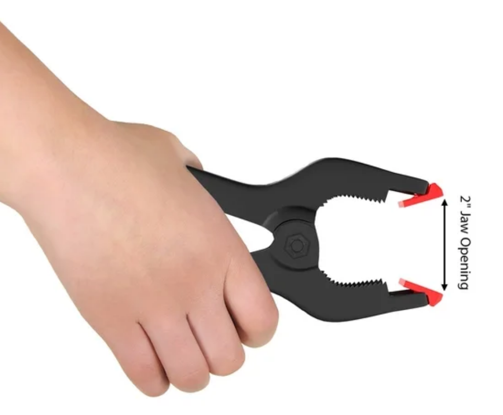
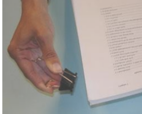
- Flexing the fingers againt a deformable spring to achieve the desired displacement. The opposite end of the spring may be supported by another part of the hand or the body or by an external structure. Lengthening or shortening of the spring provides feedback indicating if the force is too high or too low. Fig 8b shows an example in which the fingers apply force against a spring supported by the palm or thumb. The forces exerted on each side of the clamp and clip open to hold them open must be equal. Application of more or less force will cause the clamp or clip to start openning or closing. Visual to tactile feedback is used to maintain the required opening.
- Flexing the fingers against a non-deformable object to maintain control over that object. The opposite end of the object may be supported by another part of the hand or the body or by an external structure. Loss of control of the work object provides feedback if the applied force is too low, but there is no feedback if the force is too high.
- Case 1:Fig 8c shows an example in which the fingers squeeze the handles of a pivot action tool between the fingers and palm to maintain control over a work object in the chuck of the tool. The forces on the work object are amplified in proportion to the distance between the forces and the pivot point of the tool. If the task requirements are not based on conspicuous deformation of the work object, this system is essentially rigid and the tool user will have to rely on other cues, such as slippage of the work object to determine if they are exerting sufficient grip force. Application of extra force may not be apparent, users of such tools can be expected to exert excessive force to ensure control is maintained (Westling, Johansson 1984; Frederick and Armstrong 1995).
- Case 2: Fig 8d shows an example in which a rigid work object is squeezed between the fingers and thumb to prevent the object from slipping out of the hand. In this case the fingers are acting perpendicular to the surface of the object to produce friction forces acting parallel to the contact forces and possible movement of the work object. The friction forces must be greater than or equal to the finger and thumb force times the coefficient of friction between the finger and thumb force times the coefficient of friction, CoF (Frederic and Armstrong 1995; Buchholz et al. 1988; Seo et al. 2009). Equal force must be exerted by the thumb and fingers so the minimum required pinch force can be computed as:
Fpinch = Ffingers = Fthumb ≥ w / (2 × CoF)
If the pinch force and resulting friction force are insufficient to support the box's weight, the box will slip and fall out of the hand. Most people are likely to exert excess force to avoid dropping the box (Westling, Johansson 1984; Frederick and Armstrong 1995). Friction can be extrapolated from published studies or measured directly (Bobjer et al.1993; Buchholz et al. 1988; Tomlinson et al. 2013; Savescu et al. 2008; Seo et al. 2009).
For a fuller explanation and an example, see: Gripping box
For friction data and methods, see: Skin friction data & methods
- Balancing an object on the fingertips (with help from the thumb): Fig 8e shows a tray supported by the upward forces of the fingers and the downward force of the thumb. Unless the center of mass of the tray is directly over the fingertips the thumb needs to apply a downward force to prevent the tray will from rotating out of the hand. Thus the fingers must support both the weight of the tray and the downward force of the thumb. The required downward force of the thumb can be calculated as the distance between the resultant tray force and thumb force with respect to the resultant finger force. The resultant finger force can be computed as the sum of the tray weight and thumb force. The moment about the wrist can be computed as the weight of the tray times the distance between the resultant weight and the wrist. Note force disturbances exeperienced from walking or or airturbulance can produced added inertial forces on the object in the hand.
Fthumb = w × / b
Ffingers = w + Fthumb
Mwrist = c × W
This example is similar to those shown in Figs 8a and 8b in that it will be apparent from the position of the tray if the thumb force is to low or too high.
1 Deformable means that there is detectable deformation by a person with normal strength.
2 Rigid means that there is no detectable deformation by a person with normal strength.
 |
  |

| 
|  |
| Grip force = Object weight (neglecting friction) | Grip force is related to clamp or clip opening | Grip force a function of tool chuck force + possible over exertion force | Pinch force is related to weight of object and to friction (see: For a fuller explanation and an example, see: Grip box & friction) | The thumb and finger forces are related to the location of tray weight and thumb force with respect to the fingers. For a fuller explantion and an example, see: Hold tray |
| (a) | (b) | (c) | (d) | (e) |
- Studies of forces required to perform a given task in one setting, sometimes may be extrapolated to estimate force required for a similar task in another setting. Some examples include:
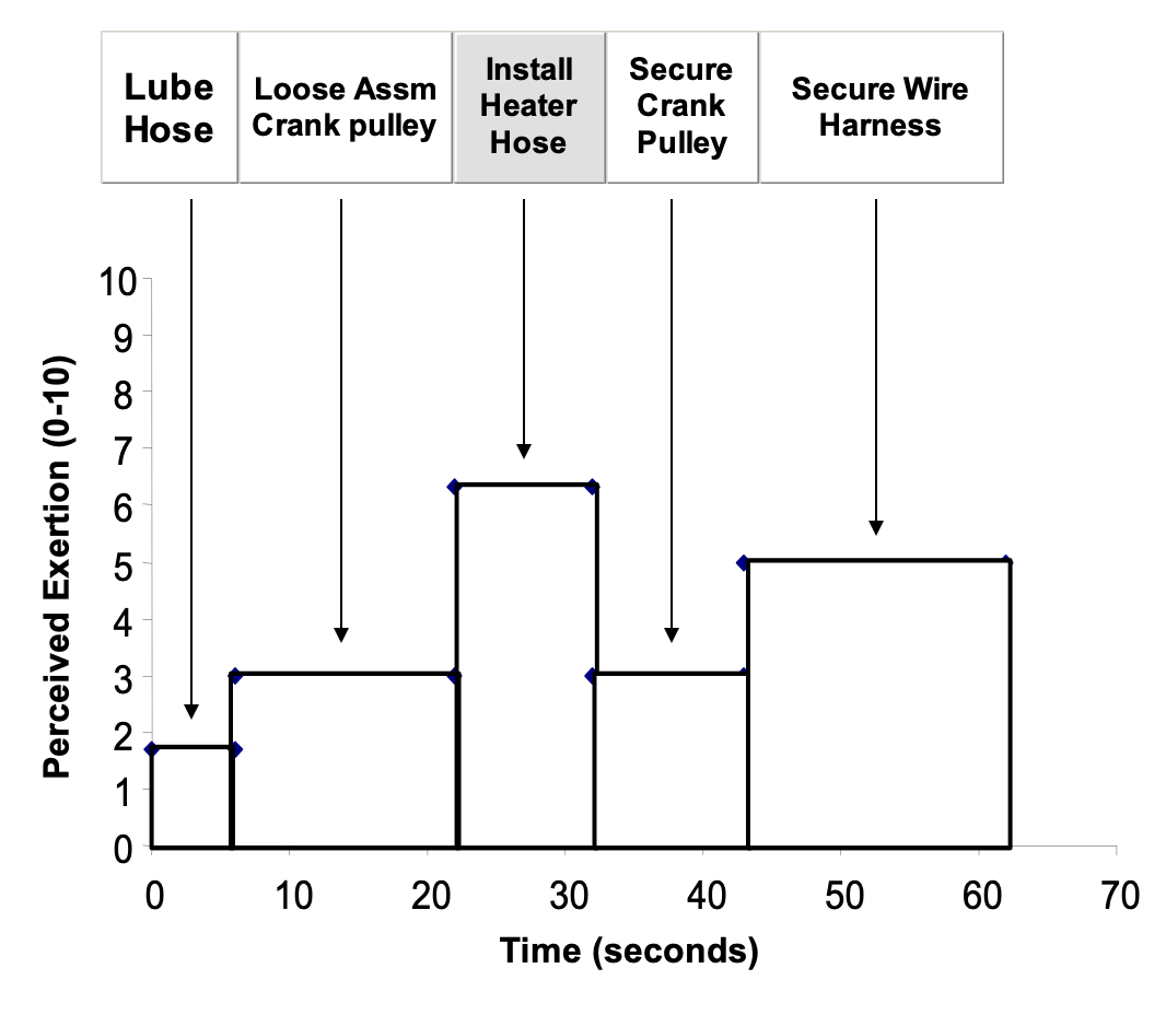
- Estimates of perceived exertion for selected auto assembly jobs (Fig 9a).
- Studies of flexible hose insertion for different hose-flange tolerances (Fig 9b)
- Studies of keyboard work on keyboards with high and low activation forces (see Fig 9c)
| Auto Assembly | Hose insertion | Keyboard forces | ||
|---|---|---|---|---|
| Action | Mean | Std Dev | ||
| Hose insert | 43 | 27 |
 |
|
| Hose Non-insert | 19 | 13 | ||
| Connectors | 32 | 24 | ||
| Powertools | 36 | 22 | ||
| Get parts | 23 | 20 | ||
| Loose assemble | 2.6 | 1.6 | ||
| Clips/RB | 3.5 | 2.7 | ||
| Inspect | 13 | 06 | ||
| Other | 34 | 27 | ||
4. Hand strength (capacity)
- The primary reasons for measuring strength is to determine the ability of a person or of persons to perform a task infrequently or frequently.
- It is important to consider all of the factors that can affect strength demands and strength capacities.
4.1 Factors affecting hand strength capacities
Individual Factors
-
1. Gender
2. Age
3. Handedness
4. Body mass, height, BMI
5. Training/experience
6. Fatigue
7. Occupation
References: see Secion 4.3 Published data
Task factors affecting strength
- Object size, shape, location, orientation --> hand, wrist, forearm posture
- Action
- Hand closing force
- hand openning or "breakaway" force
- Hand closing force + axial forces or moments
- Friction between work object and hand
- Mechanical interference between work object and hand
- Gloves (affects friction, creates mechanical interference)
- Temperature
- Strength is very sensitive to body posture if which it is measured (see Fig 10 below)
- It is important that measurements of strength be based on postures and conditions that match as closely as possible those in which the task is performed.
| |
|
 |
 |
| (a) | (b) |
(Note: strength tends to be bounded on the lower end and skewed towards the higher end of the distribution. The use of a normal approximation can lead to under and over estimating percentiles at the high and low end of the distribution. See: "4.3 Published hand strength data"
Hand strength exercise
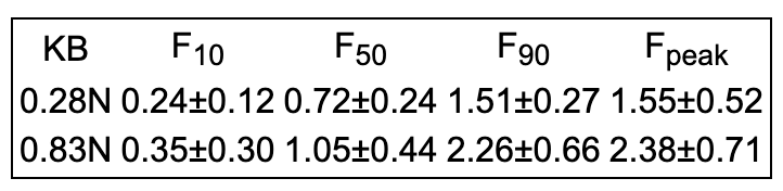
There is an abundance of published hand strength data for various populations, postures and other factors. A sample of the literature is shown in Tab 1. Google Scholar can be used to find strength data forpopulations and conditions applicatable to particular problems. There are almost no real probability studies of hand strength. Almost all of these are populations of convenience and subject some sampling bias. Also, the data may be affected by different equipment and protocols. It is advisable to look at multiple studies to find data best suited to a particular application. All of these studies include sample means and standard deviations that can be used to estimate populations percentiles. A pecentile calculator is included below.
| Reference | Study Population | Age, Hand | Equipment | Study Factors | |
|---|---|---|---|---|---|
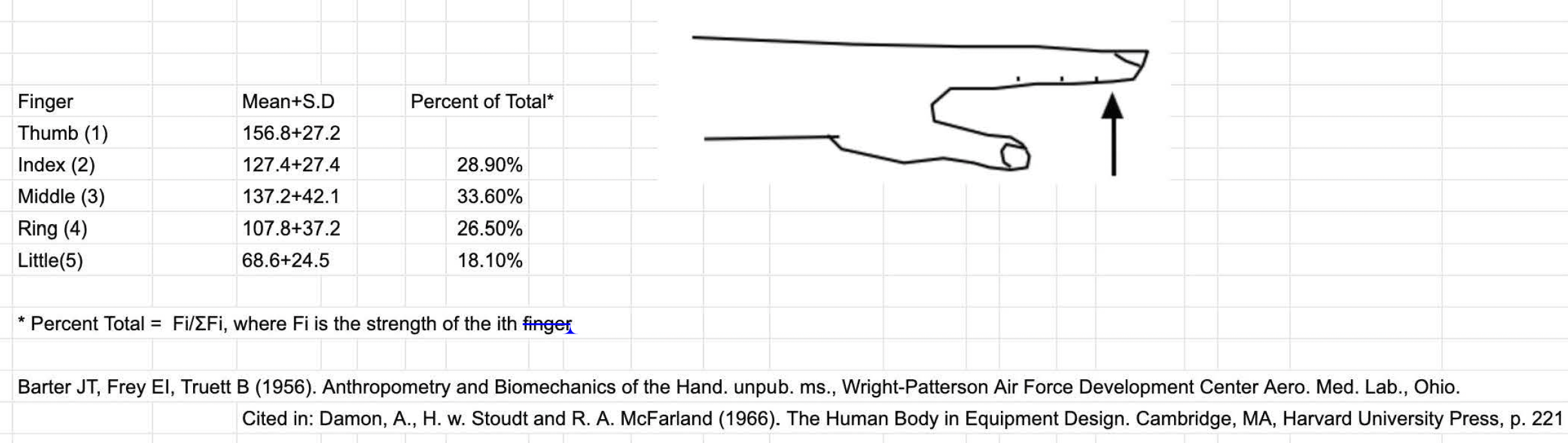
| Barter et al. (1956) | normal, halthy" AF & civilian ♂ | 19-45 years | Placed RH palm up on flat surface and exerted max force against a strain gauge bar over the finger tip | 13.25±2.75;14.18±4.30; 10.80±3.78; ±7.16±2.53 pounds 58.3±12.2; 63.0±19.1; 48.0±16.8; 20.6±11.3 newtons |
|
| Dempsey & Ayoub (1996) | 8 ♂ & 8 ♀ | 15 RH; 1 |
modified Caldwell regimen for pinch strength | Pinch width (1-3cm), pulp 2, pulp 3, chuck, and lateral pinch, neutral, flexed, extended, radial dev, ulnar dev | |
| Hazelton et al. (1975) | 30 ♂ | RH | Each finger flexed to maximum against individual force transducers. | Wirst: neutral, volar flex, dorsal flex, ular dev, radial dev. | |
| Hertzberg (1955). | 44 ♂ AF pilots | Grip (Smedley type hand dynamometer) | Grip span 1.5-5 inches; w/ & w/o gloves; also see Hamilton et al. (1994); Fransson & Winkel (1995) | ||
| Imrhan (1991) | 30 ♂; 3/4 students; 1/4 various occupations | 18-50 years | Pinch (Best Products pinch gauge) | Wrist: natural, radial deviation, ulnar deviation, dorsiflexion and palmar flexion | |
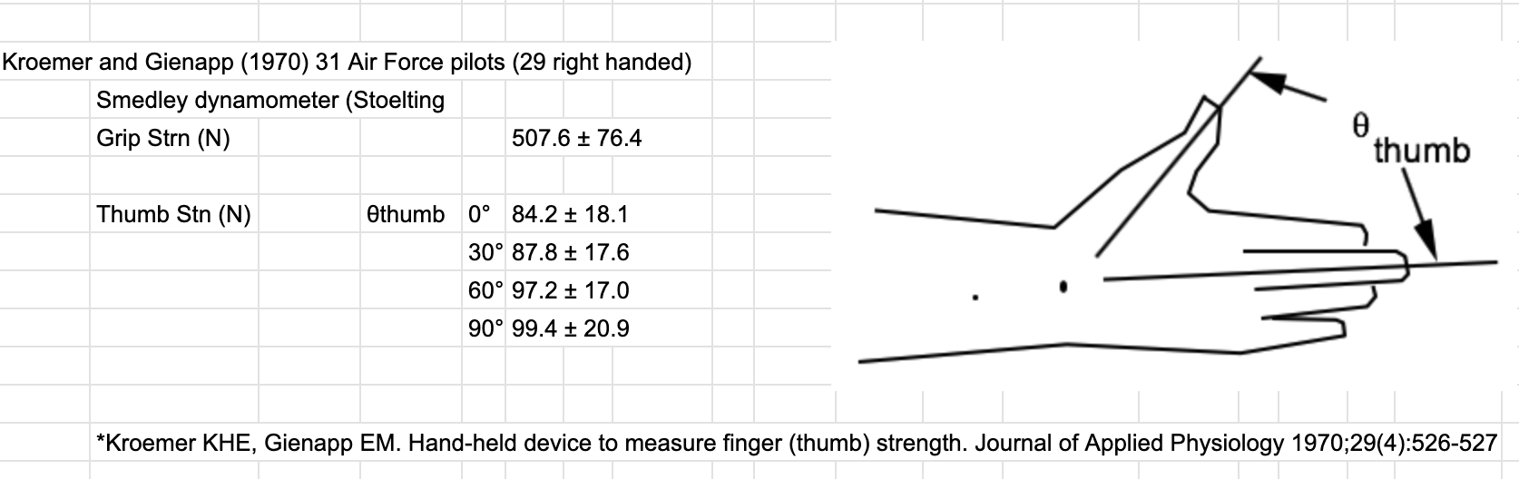
| Kroemer & Gienapp (1970) | 31 ♂ AF pilots | 29 RH, 2 LH | Custom fixter (plans described) | Thumb flexion: 0°, 30°, 60°,90° | |
| Mathiowetz et al. (1985) | 328 ♀; 310 ♂; 7 county area Milwakee, WI | 20-94 years RH & LH |
Jamar dynamometer & B&L pinch gauge |
Grip Tip pinch Palm pinch Lateral pinch |
|
| Nilsen et al. (2012) | 315 ♀ (20-94 years), 251 ♂ (20-93 years)from shopping malls, workplaces, community centres for the elderly, sports centre, and Diakonhjemmet Hospital, Oslo, Norway | Grippit instruments, grip force and pinch grip | Grip force is strongly associated with gender, age, height, and regular exercising | ||
| Dodds et al. (2016) | Meta study of age and grip strength. 60 papers, 63 different samples, 96,537 girp strengh observations. | Data for very young to very old summarized by gender, age, and area of the world | |||
Calculating percentiles
- Identify a study based on attributes relevant to your problem, e.g., gender, age, preferred hand, occupation, etc.
- Determine the strength average and standard deviation for the population of interest.
|
Calculate percentile for a given strength
Calculate:
results |
Calculate strength for a given percentile
Calculate:
results |
5.0 References
- Armstrong T, Foulke J, Joseph B, Goldstein S (1982): Investigation of cumulative trauma disorders in a poultry processing plant. Am Ind Hyg Assoc J 43(2):103-116
- Armstrong T, Foulke J, Martin B, Gerson J, Rempel D (1994): Investigation of applied forces in alphanumeric keyboard work. Am Ind Hyg Assoc J 55(1):30-35.
- Armstrong T, Choi I, Ahuja V (2008): Development of hand models for ergonomic applications.Handbook of Digital Human Modeling: Research for Appl Ergo Hum Fac Engin 20(12):1.
- Bao S, Silverstein B (2005): Estimation of hand force in ergonomic job evaluations. Ergonomics. 48(3):288-301.
- Barter J, Frey E, Truett B (1956). Anthropometry and Biomechanics of the Hand. unpub. ms., Wright-Patterson Air Force Development Center Aero. Med. Lab., Ohio. cited in: link
- Bobjer O, Johansson S, Piguet S (1993): Friction between hand and handle. Effects of oil and lard on textured and non-textured surfaces; perception of discomfort. Applied Ergonomics. 1993 Jun 1;24(3):190-202. link
- Bohannon R, Peolsson A, Massy-Westropp N, Desrosiers J, Bear-Lehman J (2006): Reference values for adult grip strength measured with a Jamar dynamometer: a descriptive meta-analysis.Physiotherapy, 92(1), pp.11-15. link
- Buchholz B, Frederick L, Armstrong T (1988): An investigation of human palmar skin friction and the effects of materials, pinch force and moisture. Ergonomics 31(3):317-325.
- Chaffin D, et al. (2006): Occupational biomechanics. Wiley Interscience.
- Dempsey P, Ayoub M (1996): The influence of gender, grasp type, pinch width and wrist position on sustained pinch strength.Intl J Indus Ergo. 17(3):259-73. link
- Dodds R, Syddall H, Cooper R, et al. (2016): Global variation in grip strength: a systematic review and meta-analysis of normative data.Age Ageing. 45:209–16. link
- Ebersole M, Armstrong T (2004): An analysis of task-based worker self-assessments of force. Proc Hum Fac Ergo Soc Ann Meet
- Ebersole M, Armstrong T (2006). Analysis of an observational rating scale for repetition, posture, and force in selected manufacturing settings. Human Factors 48(3): 487-9. 2004 Sep (Vol. 48, No. 12, pp. 1300-1304): Sage CA: Los Angeles, CA: SAGE Publications.
- Figueroa-Jacinto R, Armstrong T, Zhou W (2018): Normal force distribution and posture of a hand pressing on a flat surface. J Biomech. 79:164-72.
- Fransson C, Winkel J (1995): Hand strength: the influence of grip span and grip type. Ergonomics. 34(7):881-92.link
- Frederick L, Armstrong T. (1995): An investigation of friction and weight on pinch force. Ergonomics 38(12): 2447-2454.
- Gerard M, Armstrong T, Foulke J, Martin B (1996): Effects of stiffness on force and the development of fatigue while typing. Am Ind Hyg Assoc J 57(9):849-854.
- Grieshaber D, Armstrong T (2007): Insertion loads and forearm muscle activity during flexible hose insertion tasks. Human Factors 49(5): 786-796
- Günther C, Bürger A, Rickert M, Crispin A, Schulz C (2008): Grip strength in healthy caucasian adults: reference values. J hand surg, 33(4), 558-565. link
- Hamilton A, Balnave R, Adams R (1994): Grip strength testing reliability. J Hand Therapy. 7(3):163-70. link
- Hazelton F, Smidt G, Flatt A, Stephens R (1975): The influence of wrist position on the force produced by the finger flexors. Journal of Biomechanics. 8(5):301-6.
- Hertzberg H (1955). Some Contributions of Applied Physical Anthropologyto Human Engineering.Ann NY Acad Sci 63:616- 629. link
- Imrhan S (1991): The influence of wrist position on different types of pinch strength.Appl Ergo, 22(6), 379-384. J Appl Phys 1970;29(4):526-527 link
- Kroemer K, Gienapp E (1970): Hand-held device to measure finger (thumb) strenght. J Appl Phys. 29(4):526-7.
- Koppelaar E, Wells R (2005): Comparison of measurement methods for quantifying hand force. Ergonomics. 48(8):983-1007.
- LeVeau B (1992) Williams and Lissner's biomechanics of human motion. Pennsylvania: Saunders" PP:206-213.
- MacDermid J, Lee A, Richards R, Roth J (2004): Individual finger strength:: Are the ulnar digits “powerful”?. Journal of Hand Therapy. 17(3):364-7.
- Marshall M, Armstrong T, Ebersole M (2004): Verbal estimation of peak exertion intensity. Human Factors 46(4):697-710, 2004.
- Marshall M, Armstrong T. Observational assessment of forceful exertion and the perceived force demands of daily activities. J Occup Rehab 14(4): 281-294,.
- Mathiowetz, V, Kashman, N, Volland, G, Weber, K, Dowe, M, Roger, S. (1985): Grip and pinch strength: Normative data for adults. Arch Phys Med Rehab, 66:69 – 76 link
- Nilsen T, Hermann M, Eriksen C, Dagfinrud H, Mowinckel P, Kjeken I (2012): Grip force and pinch grip in an adult population: reference values and factors associated with grip force. Scandinavian journal of occupational therapy, 19(3), pp.288-296 link
- Seo N, Armstrong T, Ashton-Miller J, Chaffin D (2007): The effect of torque direction and cylindrical handle diameter on the coupling between the hand and a cylindrical handle. J biomech. 40(14):3236-43.
- Seo N, Armstrong T, Drinkaus P (2009): A Comparison of Two Methods of Measuring Static Coefficient of Friction at Low Normal Forces: A Pilot Study. Ergonomics 52(1):121-135.
- Savescu A, Latash M, Zatsiorsky V (2008): A technique to determine friction at the fingertips. J appl biomech. 24(1):43-50.
- Schmidt R, Toews J (1970): Grip strength as measured by the Jamar dynamometer.Arch Physical Med Rehab, 51(6), 321-327.
- Takala E, Toivonen R (2023): Placement of forearm surface EMG electrodes in the assessment of hand loading in manual tasks. Ergonomics. 56(7):1159-66.
- Tomlinson S, Lewis R, Carre M, Franklin S (2013): Human finger friction in contacts with ridged surfaces. Wear. 301(1-2):330-7. link
- Ulin S, Ways C, Armstrong T, Snook S (1990): Perceived exertion and discomfort versus work height with a pistol-shaped screwdriver. Am Indus Hyg Assoc J. 51(11):588-94.
- Westling G, Johansson R (1984): Factors influencing the force control during precision grip. Exp brain res, 53, 277-284. link
- Young J, Woolley C, Armstrong T, Ashton-Miller J (2009): Hand-Handhold Coupling: Effect of Handle Shape, Orientation, and Friction on Breakaway Strength.Human Factors 51(5):705-717. link