![]()
Finite Element Analysis of Dimensional
Differences
Involving the Width of the Joint Space
Brien R. Lang, DDS, MS
Rui-Feng Wang, BS
Byungsik Kang, PhD
Lisa A. Lang, DDS, MS
Michael E. Razzoog, DDS, MS, MPH
INTRODUCTION
The Procera AllCeram bridge is created by the Procera System and finalized by using Procera AllCeram veneering porcelain to complete the anatomic form of the bridge. The strength needed in an all-ceramic fixed bridge, so that it can be used in all locations in both dental arches is the research focus of several projects conducted by investigators from the Center For Excellence.
The amount of joint space was another questions that was addressed by the Center investigators. The finite element model created for earlier studies was dimensioned with a joint space of 0.050 mms. The model was created with the Procera Fusing material flush with the margins of the aluminum oxide material forming the joint. The fusing material at the joint site was then covered with the Procera AllCeram veneer porcelain to complete the model. This was the protocol followed in designing the models because this was the laboratory protocol used in fabrication of the bridge by technicians.
Of concern to the Center investigators was the possibility that the joint space created by the technician would exceed the 0.050 mm and would a wider gap influence the strength of the joint. To answer this questions another series of models were made using the FEA bridge model with the 12.0 mm pontic, as illustrated in Fig. 1.
Fig. 1. FEA Models to Examine Load to Fracture
When Varying the Joint Space
This model consisted of only the copings and the pontic in the aluminum oxide material joined by the Procera Fusing material. Procera bridge models were designed with joint spaces varying by 0.050 mm ranging from 0.050 mm to 0.500 mm. A second series of models were also created in which varying joint spaces were used with the addition of a layer of fusing material around the joint. The questioned addressed by this second series of models dealt with the influence covering the joint and a portion of the aluminum oxide margins with fusing material might have on the strength of the joint. The load to fracture data for the Procera AllCeram bridges with varying joint space and the external layer of fusing material are illustrated in Fig. 2.
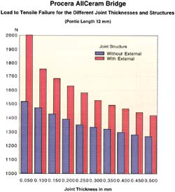
Fig. 2. Load to Fracture Data When Varying the
Joint Space and Applying External Layer
Each model was subjected to a load of 2000 N, and the Von Mises values were recorded for the elements in the joint. Those elements that recorded a Von Mises value in excess of the yield point of the Procera Fusing material (80 MPa) were examined in the XX axis to determine the nature of the dominant stress. Those elements in tension were considered to have fractured. The data were further examined to determine the load at which the Von Mises value exceeded the yield point of the fusing material.
The 0.050 mm joint space was the strongest (1500 N) in the absence of the external layer of fusing material. The 0.500 mm joint space (1275 N) as expected was the weakest. However, in all instances the strength of the joint exceeded the 800 N target. What was particularly interesting in this study was the influence of the layer of fusing material wrapped around the margins of the aluminum oxide in the joint site. In the case of the 0.050 mm joint space, the strength exceeded the load of 2000 N. All of the joint spaces studied were significantly strengthened by the external layer. This finding would seem to suggest a material of greater tensile strength than the veneering porcelain covering the joint margins might produce a stronger joint. Another suggestion would be to develop a new veneering material with a yield points greater than the current 68 MPa of the Procera AllCeram porcelain.
SUMMARY of the RESEARCH FINDINGS
Within the limitations of this study the following can be concluded:
The 0.050 mm joint space was the strongest (1500 N) in the absence of the external layer of fusing material. The 0.500 mm joint space (1275 N) as expected was the weakest. However, in all instances the strength of the joint exceeded the 800 N target.
Close window to continue.