Tutorial
ĀFlowsheet
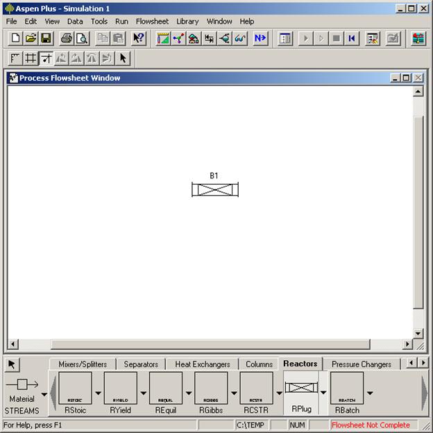
We will start creating our flowsheet by adding a reactor from Model Library toolbar to the Process Flowsheet Window. Select the Reactors tab on the Model Library toolbar. The built-in models for reactors are RSTOICH, RYIELD, REQUIL, RGIBBS, RCSTR, RPLUG and RBATCH. Clicking the down arrow to the right of the model gives different symbol choices for the user to insert into the flowsheet.
Select the left bottom symbol after expanding the RPLUG symbols and draw a rectangle where you want to insert on the Process Flowsheet Window. Now the Process Flowsheet Window should have an icon representing your plug flow reactor as shown in the next picture. In Aspen Plus™ terminology it is a Block. Hence, it is named by default as B1.
Now select the STREAMS section of the Model Library toolbar. Aspen Plus™ has three different stream categories, Material, Heat and Work, as shown in the next figure. Material Stream is the default icon shown.
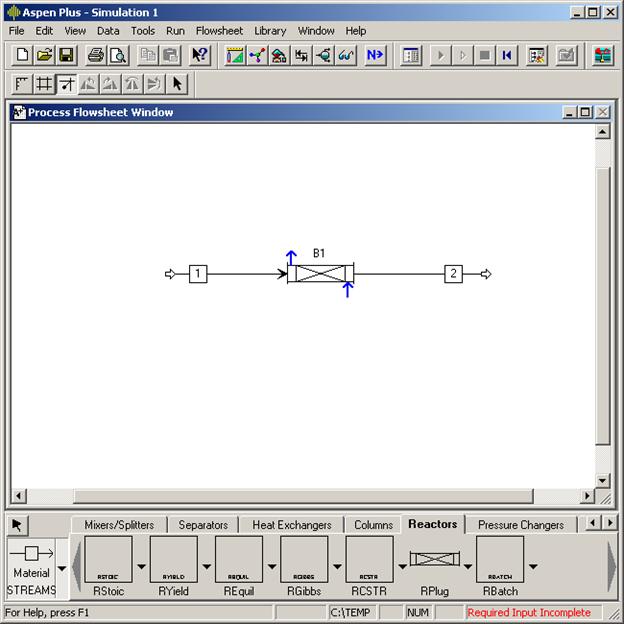
After selecting the Material Stream icon draw a line on the flowsheet from a point to the left of the block B1 towards B1. You will realize two highlighted arrows as you approach the block. The red line is the required FEED connection to RPLUG. The blue line is the optional heating or cooling fluid entrance. Select the red arrow to connect your feed stream.

The stream is named as S1 by default. Similarly connect your product stream to the block. When you are done your flowsheet should look like the following picture. There will be still two highlighted blue arrows for heat duty requirements. As these streams are optional we can proceed with the next activity. Note the change in the status message from Flowsheet Not Complete to Required Input Incomplete. Clicking on the arrow above the streams icon will hide the blue arrows and let you freely move the icons on your flowsheet and arrange them to your liking.
One thing that might be useful is to align the streams and blocks. To do that, draw a large rectangle to select all of your icons on the flowsheet and then right click to activate a pop up menu. Select the Align Blocks entry from this pop up menu. If you do not select all icons, but only one, a different pop up menu will be activated.
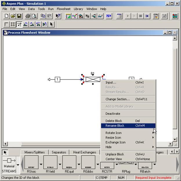
You can also rename the objects you insert onto the flowsheet. To do that highlight the object you want to rename and click the right mouse button. A pop up menu will be activated. Select the Rename Block entry from it. The next picture shows the rename operation for the block B1.
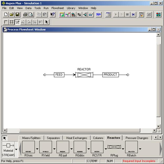
After renaming stream S1 to FEED, stream S2 to PRODUCT and B1 to REACTOR the flowsheet will look like the following picture. At this stage the flowsheet is complete and the rest of the specification is done with Input Forms.
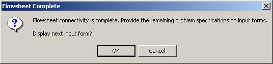
Whenever you have doubts on what to do next, the lowest energy action is to click the Next Button.
This button will take you to next part of the specification or tell you what is missing from your specifications.
ĀĀĀĀĀĀĀĀĀĀĀ At this point, we know that the flowsheet is complete. However, we also know that parts of the required input are missing. Remember, if we are not sure what to do next we click the Next Button.